

Table of Contents
How to create your own Arduino circuit board?
Arduino has revolutionized electronics with an open-source hardware platform accessible to everyone. Numerous boards of Arduino are already available in the market.
Learn all about designing and manufacturing your own Arduino PCB. In this complete guide, you will learn the fundamentals of Arduino PCB design, components and a step-by-step guide in designing your own Arduino circuit board.
What is an Arduino PCB?
Arduino is the opensource platform with both PCB and built-in Arduino software’s. The Arduino PCB is a custom-designed electronic circuit board that mimics or expands the capacity established by a standard Arduino board. It includes a microcontroller, power management circuitry, and a set of digital and analog input/output (I/O) pins to connect to switches, sensors, motors, and other devices.

| Parameter | Design Specification | Typical Implementation Scheme (Uno R3) |
| Input Voltage Range | 7-12V DC (through DC jack) or 5V USB direct connection | LM7805 linear regulator (5V/1A output) |
| Core Voltage Conversion | 5V → 3.3V (some new MCUs) | AMS1117-3.3 (power supply for I/O level-shift chip) |
| Decoupling Capacitor Layout | 100nF ceramic capacitor attached to MCU power pin ≤ 3mm, 10μF tantalum capacitor placed at regulator output | 0805 package capacitor, impedance ≤ 0.1Ω@100MHz |
| Over-current Protection | Self-recovering fuse (500mA) in series in USB power supply path | PTC model MF -MSMF050 |
| Interface Type | Electrical Characteristics | PCB Design Rules |
| Digital I/O (D0-D13) | TTL level (0V/5V), driving capacity 20mA (single pin) | Signal line width ≥ 8mil, and the distance from the power line ≥ 15mil |
| Analog Input (A0-A5) | 10 bit ADC (0-5V range), input impedance 100MΩ | Add RC low-pass filtering (R = 1kΩ, C = 100nF) |
| PWM Output | 490Hz frequency, 8 bit resolution | Avoid long traces (recommended ≤ 50mm) to reduce EMI radiation |
| Communication Interface | SPI (SCK@4MHz) I²C (100kHz standard mode) UART (115200bps) | Differential pair control (such as MISO/MOSI length difference ≤ 5mm) |
| Design Requirements | Arduino Uno Scheme | Arduino Mega 2560 Scheme |
| MCU Selection | ATmega328P (32KB Flash, 2KB RAM) | ATmega2560 (256KB Flash, 8KB RAM) |
| Power Supply Topology | Single-path 5V output (automatic switching between USB and DC jack) | Dual-path independent power supply (digital/analog power separation) |
| I/O Expansion Capability | 14 digital + 6 analog | 54 digital + 16 analog |
| Communication Interface | 1 set of hardware SPI/I²C/UART | 4 sets of UART, 2 sets of I²C, SPI can be multiplexed to multiple pins |
| PCB Layers | 2-layer (low cost) | 4-layer (with independent power/ground layers) |
Arduino PCB is of various types and shapes. Some major Arduino board types include:
| Model | Size(mm) | Number of layers | Applicable scenes |
| Uno R3 | 68.6×53.4 | 2 | Education/Prototyping |
| Mega 2560 | 101.5×53.3 | 4 | Industrial Extended Scenarios |
| Nano | 45×18 | 2 | Embedded Devices |
- Arduino Uno (Microcontroller ATmega328P)
- Arduino Micro (Microcontroller ATmega32u4)
- Arduino Nano (Microcontroller ATmega328P)
- Arduino Mega (Microcontroller ATmega2560)
- Arduino Lily-Pad (Microcontroller ATmega32u4)
- Arduino Zero (Microcontroller Atmel SAMD21G18)
Let’s check out some of the major components found in Arduino PCB:
| Component | Description |
| Processor (Microcontroller) | Normally, its ATmega328P or ATmega2560. It is chosen based on what processing power, GPIO pin out, and specific project needs. |
| Power Supply | Regulates voltage for microcontroller and other components. It has a voltage regulator for 5V or 3.3V systems. |
| Crystal Oscillator | Generates a 16MHz clock pulse (for microcontroller). External capacitors may help with oscillation stabilization. |
| Input/Output Pins | Used to interact with sensors, actuators, & other peripherals. It requires proper pull-up/pull-down resistors. |
| USB-to-Serial Converter | The signals from USB are converted to UART. |
| Reset Circuit | It has a push button to autonomously reset the microcontroller if needed. |
| Decoupling Capacitors | Set close to the power supply to remove noise with stable voltage. |
How does an Arduino Board Work?
In the working process of the Arduino board, signal flow is a systematic process. It is first the responsibility of sensors to detect different physical quantities of the external world, such as temperature, light intensity, etc.
Thereafter, the signals which are emitted from the sensors tend to be normally subject to signal conditioning. This includes processes such as amplifying weak signals or eliminating noise in a bid to guarantee signal quality and accuracy.
Next, the conditioned analog signal is directed to an ADC (Analog to Digital Converter) for conversion. In an Arduino, a 10 bit ADC is commonly employed, meaning that it can convert an analog signal to a digital value of 0 1023, allowing the microcontroller to process it digitally.
Next, the microcontroller (Arduino) interprets these digital signals according to a pre-stored program, for example, to make decisions or calculate values based on data from sensors.
Finally, the processed data is output to GPIO pins, and these can be used to supply power to other devices such as LEDs, motors, etc., thus allowing control of or interfacing with external devices.

How does Arduino Power Management Subsystem Work?
Within the Arduino board, the power management system exploits a dual voltage design in a bid to handle the needs of the different components.
For the 5V rail, AMS1117 5.0 regulator can be utilized, which supports up to a maximum input voltage of 16V. It can regulate stable higher input voltages to 5V and provide the power to those devices that should operate at 5V operating voltage.
3.3V rail is capable of being supported by the RT9193 33GB with an output precision of ±1.5% and providing a precise and stable 3.3V voltage.
| Parameters | ATmega328P | STM32F103 |
| Core Architecture | 8-bit AVR | 32-bit ARM Cortex-M3 |
| PCB Layout Requirements | 4-layer board, line width ≥8mil | 6-layer board with ±7% impedance control |
| BGA Package | Not Supported | Requires 0.4mm pitch wiring |
How to Design Your Arduino PCB?
Step 1:
Obtain a Schematic Diagram
Use PCB design software like Eagle, Ki-Cad or Altium Design to draw the schematic diagram of your Arduino PCB. This diagram will give you a wiring diagram on how all of the components hook up (This will be your “blueprint” for your circuit).


Step 2:
Verify the Arduino Schematic
ESD Protection of USB Interface
Within the Arduino schematic design, the protection of the ESD of the USB interface is very critical and must be provided with TVS diodes (such as ESD5Z3.3T1) so that the circuit is protected from electrostatic destruction of the USB interface.
Crystal Layout
Crystal mounting, to stay out of the MCU ≤ 15mm and packet ground treatment. This is because the MCU crystal to provide clock signals, proximity mounting may reduce signal loss of transmission and interference, packet ground can also reduce electromagnetic interference.
Comparison of Laminated Structure
When designing Arduino PCBs, the laminate structure affects EMI, and structures such as double-layer boards and multilayer boards are evaluated by comparing the results of EMI tests. Double-layer boards are simple, low cost but poor EMI control, multilayer boards can be layer layout, good control of EMI, the design should depend on the function, cost and EMC standards to choose the correct structure.
| Type | Thickness | EMI@100MHz |
| double-layer | 1.6mm | 48dB |
| four-layer | 1.6mm | 32dB |
DFM Check List
| Parameters | Requirement | Purpose |
| Minimum line width/spacing | 6mil/6mil | Avoid uneven etching |
| Overcap Oil | Hole diameter ≥0.3mm | Prevents soldering shorts |
| V-CUT depth | Plate thickness 1/3±0.1mm | Ensure the reliability of depaneling |
Step 3:
Route the Traces
Connect Electronic Components with PCB Layout Editor. Keep traces as short as possible and do not cross them to avoid signal interference. Power and ground connections are usually carrying orders of magnitude more current so you’ll definitely want wider traces for those runs.
Step 4:
Generate Gerber Files
After the full PCB layout, create Gerber files. These files contain all the information required to manufacture the Arduino PCB. Verify that the files are correctly included in the layers and components.
On KiCad, once you are done with making the designs and schematic diagrams, check the layers you want to generate. Then, click Plot again to generate the layers.
Step 5:
Manufacture Your PCB
Send the Arduino PCB or send Gerber files to manufacturers like ELEPCB or do it yourself. After that PCB is made, let us start assembling the Arduino PCB.
Submit Design Documents For A Quick 24-hour Quote!
Assembling Arduino PCB
Initial Check
Verify that the SMT process is in accordance with the requirements, such as equipment accuracy, process parameters (such as temperature profile, printing pressure, etc.) . Along with conducting the compatibility tests on the shield to ensure it is compatible with the Arduino PCB.
Stencil Design
- In case of 0402 components, the stencil opening ratio is standard at 1:0.9, which is targeted at preventing tin beads.
- For QFN package components, the stencil is designed to protrude the pins by 0.1mm to improve solder creepage quantity and ensure soldering quality.
Shield Compatibility Testing
- Level compatibility: A 3.3V buffer (e.g. 74LVC245) is used in the interface for 5V signals to ensure stable transition among different level signals.
- Mechanical fit: The edges of the PCB are chamfered to a chamfer dimension of 0.3mm to satisfy IDC socket tolerances and ensure precision and stability in the mechanical fit.
- Durability test: plugging and unplugging test 500 times is conducted, and the contact resistance after plugging and unplugging should be ≤20mΩ (according to the MIL-STD-1344 standard).
Step 1:
Gather Components
Step 2:
Solder the Components
Once you created the schematic for the PCB, collect all the components required for your Arduino PCB, including the microcontroller, resistors, capacitors, and connectors.
Solder the various components onto the PCB, paying attention not to short, and soldering the smaller parts first. Try to use a soldering iron that has a fine tip.
Step 3:
Test the PCB
Step 4:
Upload the Bootloader
Make sure to test assembled PCB that all components are working correctly. If needed, ensure no shorts and confirm with a multimeter that power in is correct voltage.
Upload the Arduino bootloader to the microcontroller using the custom Arduino PCB. If uploading the bootloader through an FTDI (or compatible) USB to Serial converter, connect the PCB to your computer.
Step 5:
Upload Your Sketch
After the bootloader is installed, you are then able to upload your Arduino sketch to the microcontroller. Use the debug information your sketch provides to verify the PCB functions as expected!
Commercial Considerations
There are different methods of quoting in bulk for major devices such as Arduino Electronics. ELEPCB possesses a professional BOM team to help you with 1 to 1 quotation service.
Our procurement channels are diversified and most brands possess years of collaboration with the original manufacturers, for the individual age-sensitive components, we will help you find the appropriate age of the normal channels, if required you can also let us know about the needs of customized pcb.
PCB BOM Cost

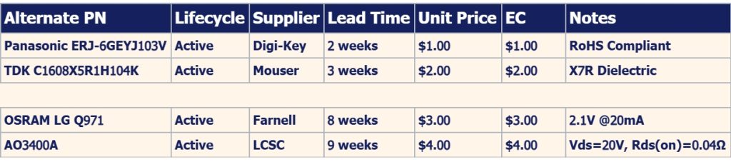
We also take into account many other relevant elements, including:
- Temperature Range
- Moisture Sensitivity
- IPC Class
- Impedance
Submit Design Documents For A Quick 24-hour Quote!
Conclusion
Creating your very own Arduino PCB is a daunting but satisfying task that can add a new level to your electronics projects. You can design it and then manufacture it yourself, according to your budget. Of course, if you need a professional and experienced manufacturer to help you mass-produce your design, ELEPCB will provide you with all the services you need.
FAQs
A1:
- Thermal management: If using a linear voltage regulator, add a heatsink as necessary.
- Trace Width: Power traces should be wide enough to prevent overheating when carrying current. A PCB trace width calculator can figure out what the width should be.
- Component Layout: Do not position components sensitive to heat (for example, capacitors) close to other components that generate high thermal power, such as voltage regulators.
A2:
- Short Circuit Testing: Carry out short circuit testing with the help of a multimeter.
- Check Power Supply: Ensure the voltage regulator is providing the correct voltage (5V or 3.3V) to the microcontroller and other components.
- Check your connections: Ensure there are no cold solder joints or unsoldered pins, particularly in the vicinity of the microcontroller and USB-to-serial converter.
- Bootloader Issues: If the microcontroller is not responding whatsoever, reload the Arduino bootloader using an external programmer such as an AVR ISP.
A3:
Common pitfalls include incorrect component placement, poor trace routing, and incorrect power supply design. Check your schematic and layout thoroughly to avoid these issues.
A4:
Step 1: Solder the CNC shield (e.g., Arduino CNC Shield V3.0) onto the Arduino Uno board.
Step 2: Wire the stepper motor drivers (e.g., A4988) into the X, Y, and Z axis pins of the CNC shield.
Step 3: Download and install Arduino IDE (Integrated Development Environment).
Step 4: Download GRBL firmware from GitHub (typically in.zip file format).
Step 5: In Arduino IDE, select Sketch→Include Library→Add.ZIP Library., then select the grbl folder in the downloaded GRBL firmware folder to install GRBL as an Arduino library.
Step 6: In Arduino IDE, select File→Examples→grbl→grblUpload.
Step 7: Select the correct Arduino board and COM port, and press the upload button to upload the GRBL firmware onto the Arduino board.
Step 8: Open the serial monitor in Arduino IDE, set the baud rate to 115200.
Step 9: Enter ” ” to view the existing GRBL settings and adjust them according to the specific parameters of the CNC machine, such as the stepper motor steps, top speed, acceleration, etc.
					// Include the GRBL library
#include <grbl.h>

GRBL grbl;

// The setup function runs once when the Arduino starts
void setup() {
    Serial.begin(115200);  // Initialize serial communication at 115200 baud rate
    grbl.init();  // Initialize GRBL
}

// The loop function runs continuously after setup
void loop() {
    // Send a G - code instruction to move to coordinates (10, 10, 5)
    grbl.sendGCode("G0 X10 Y10 Z5");

    // Wait until the movement is complete
    while (grbl.isMoving()) {
        delay(100);
    }

    // Close the GRBL connection
    grbl.close();

    // Add a delay to avoid rapid repetition
    delay(1000);
}


CONTACT US






 English
  Italian
  Hungarian