

Table of Contents
Effective PCB thermal management is not merely a design consideration—it is a fundamental requirement for reliability. Up to 55% of failures of electronic circuit boards are caused by heat!
I vividly remember the first (and hopefully last) time a circuit board caught fire. Smoke first emerged from a resistor and the flames quickly spread to the nearby decoupling capacitors. Fortunately, the damage was minimal and most of the components could be repaired. The cause was not a short circuit, but rather a design flaw in the PCB layout.
This article serves as a comprehensive guide to PCB thermal management. We will explore the root causes of heat generation, delve into the principles of heat transfer, and provide actionable strategies—from material selection and layout optimization to active thermal management solutions—to ensure your designs remain cool, stable, and reliable.

Why is Thermal Management Critical in PCB Design?
Electronic equipment in the operation process will produce a certain amount of heat, which never leads to a rapid increase in the internal temperature of the equipment.
Increases in temperature affect the operation of both active and passive components within integrated circuits, resulting in malfunction or fail completely. Such failures include thermal runaway, junction failure, metallisation failure, corrosion, resistance drift and electromigration diffusion.

Key Causes of PCB Heat Generation and Overheating
So what are the factors that cause PCBs to generate too much heat?
- Ongoing miniaturization means more compact PCBs with components placed closely together. This results in increased power density and heat concentration.
- Modern electronic components themselves generate significant amounts of heat. For instance, high-brightness LEDs, power devices, ICs, and CPUs are heat-producers.
- Heat generated by current through PCB lines. According to Joule’s law, heat is generated in the resistance when current passes through conductors such as wires and pads on the PCB.
- High-frequency signal loss: In high-frequency circuits, the signal will generate heat due to dielectric loss, conductor loss, etc. during the PCB transmission process.
Understanding Heat Transfer Mechanisms
After understanding the causes of heat generation, let us delve deeper into the principles and mechanisms of heat transfer to better comprehend PCB heat dissipation techniques.
Three Ways of Heat Transfering
There are three main ways that heat transfers: conduction, convection and radiation.
- Conduction: Heat transfers through solids. On PCBs, it primarily transfers through the copper alignments and substrates.
- Convection: Heat transfers through fluid motion. Air movement around the PCB induces convection.
- Radiation: Heat radiates as infrared energy. Radiative cooling from PCB surfaces.
The principal methods of PCB thermal control are conduction across the board and air convection. Radiation is only of significance at very high temperatures.
The Concept of Thermal Resistance
Thermal resistance indicates the temperature difference when heat flows through a material. Low resistance enables faster heat transfer.
- How to reduce thermal resistance?
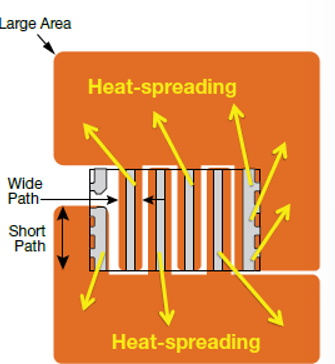
- Shorten the thermal path between components and heat sinks
- Increase the cross-sectional area for heat flow
- Select materials with higher thermal conductivity
Efficient PCB Thermal Management Techniques
Efficient PCB thermal management requires a combination of simulation, testing, and practical design strategies.
PCB Layout Optimization for Better Heat Dissipation
The general strategy for thermal management involves designing the PCB itself in such a way as to maximize heat dissipation.
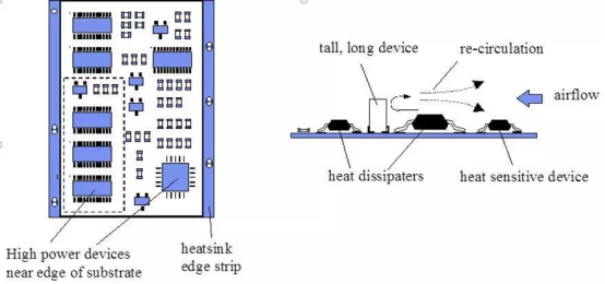
Manage Component Placement
Grouping many heat-generating components creates hotspots. Therefore:
- Distribute high-power components uniformly to prevent local hotspots.
- Isolate heat-generating components with a 3mm minimum spacing. Avoid placing them at the corners or edges of the board unless there are heat dissipating tools.
- Isolate heat-sensitive ICs from hot components.
- Position heat sinks in an optimal location to dissipate heat from hot components.
- Mount ICs horizontally for air convection between fins.
- Place temperature-sensitive devices in the coolest parts of the PCB, such as the bottom of the board.
- Separate high-power traces from heat-sensitive traces.
Select Materials Good for Heat Dissipation
Match coefficient of thermal expansion (CTE) between components and board to minimize thermal stresses.
| Material | Thermal Conductivity (W/m·K) | Key Properties | Best For |
| Aluminum Nitride (AlN) | 150–220 | Very high conductivity, low CTE mismatch | Extreme high-power, RF |
| Copper Core PCB | 380–400 (core) | Efficient heat spreading, dielectric layer | High-power LEDs, automotive |
| Alumina (Al₂O₃) | 20–30 | Good conductivity, cost-effective | Power modules, sensors |
| Aluminum Core PCB | 200–210 (core) | Lightweight, dielectric limits conduction | Medium-power applications |
| Quartz Laminate | 1–2 | Low CTE, stable at high temps | Aerospace, precision instruments |
| FR-4 | 0.3–0.4 | Low cost, poor thermal performance | Low-power consumer electronics |
In addition to choosing suitable materials for the PCB substrate, thermal dissipation can be improved by increasing its thickness.
| Substrate Thickness | Thermal Capacity Index | Typical Application Scenarios |
| 0.8 mm | 1.0x | Devices with <5W power consumption |
| 1.6 mm | 2.3x | Industrial controllers |
| 2.4 mm | 3.8x | Electric vehicle charging modules |
Consider Copper Weights
Thicker copper has lower thermal resistance:
- Use heavy copper layers of 2oz/ft2 or more for high-power areas.
- Wide copper traces quickly conduct heat away from hot devices.
- Solid copper planes spread heat on the PCB.
- You can also design a large copper pour or grounding copper foil to help dissipate the heat.
- Add Thermal Vias
- Thermal vias provide low-resistance conduction paths through the PCB:
- Place an array of vias near hot devices.
- Copper plug filled vias are better than hollow vias.
Place vias beneath the thermal pad of the hot device for direct cooling.
Prioritize Power and Ground Planes
Good power and ground planes reduce PCB temperatures:
- Create continuous power and ground copper planes on inner layers.
- Connect the planes to a larger copper fill outer layer for heat spreading.
- Isolate power and ground planes slightly to reduce capacitive coupling.
In brief, thermal performance must be considered by designers during layout and material selection.
Utilize Active Cooling Techniques
Wherever the PCB design itself is inadequate for heat removal, active methods of heat removal must be employed then.
Heat Sinks
Heat sinks are channels or fins mounted on hot components for the sake of providing a greater surface area to cool. Some of the most significant elements of heat sink design are:
- Material thermal conductivity – Aluminum or Copper optimum
- Surface area for enhanced heat transfer
- Proximity to hot components
- Thermal interface material like adhesive or grease between component and sink
- Heat sink shape, spacing, and orientation with respect to airflow
Heat sinks provide passive cooling with zero power consumption. They are sufficient for medium heat fluxes.
Cooling Fans
Fans provide forced-air convection:
- Airflow increases heat transfer from board surfaces and fins.
- Heat conduction to ambient air is increased.
- Correct orientation to guide airflow effectively is very important.
Fans work best in combination with heat sinks and heat pipes. Fans can actively cool boards of very high power density.
Heat Pipes
Heat pipes allow for very efficient heat transfer:
- They are sealed with fluid that evaporates and condenses, carrying heat.
- The internal wick structure recycles condensed liquid via capillary action.
- No moving parts allow low-wear, quiet operation.
Limitations are the fixed heat transfer capacity and need for careful alignment. Overall, heat pipes provide excellent cooling for PCB hotspots.
Thermal Modeling and Testing
Optimized PCB thermal management starts at the design level through advanced simulation software such as ANSYS, SolidWorks Thermal, and Thermal Desktop.
The software allows designers to predict temperature distribution, identify layout-induced hotspots, analyze heat flow, evaluate the performance of heat sinks, and compare the thermal impact of different materials or cooling systems.
After prototypes are produced, PCB thermal testing confirms these simulations under actual conditions. Infrared cameras capture precisely hotspots, thermocouples measure actual operating temperatures, wind tunnels test airflow cooling efficiency, and shock or vibration tests quantitatively thermal cycling stresses.
Combining simulation with testing guarantees reliable thermal performance, optimized cooling designs, and improved long-term PCB reliability.
Conclusion
In short, correct thermal management is critical from the initial design stage to the production of efficient, high-performance PCBs. Techniques of thermal design facilitate heat dissipation through conduction, convection, and radiation. These are the best placement of the components, the substrate materials suitable for thermal reasons, copper weights, thermal vias, and power/ground planes.
When PCB design alone is inadequate, active cooling solutions like heat sinks, fans, and heat pipes are the remedies. Try to use thermal modeling simulation tools and testing to help improve heat dissipation.
Looking for more advanced design guidelines or having specific challenges? Contact our engineering team for consultation!





 English
  Italian
  Hungarian