

Table of Contents
Through a VGA interface, a pin VGA PCB is intended to promote video signal transmission. This PCB ensures that the VGA harbor and the rest of the circuit have valid electrical connections by acting as the VGA connectors’ spine.
Follow ELEPCB to maximize its utility by having a thorough understanding of its design, components, and applications.
What is a VGA Plug in PCB?
A Pin VGA PCB maintains optimal direction and electrical integrity to ensure consistent signal transmission. VGA is a widely used analog video standard that sends visual information from a source device, such as a computer, to a display, like a projector or a screen. Despite the popularity of computer interfaces like HDMI and DisplayPort, VGA is still used in mechanical applications, low-cost exhibition setups, and frameworks.
VGA Connector Pins and Their Functions
VGA Socket Pinout

VGA interface is a 15 pin D-Sub (DE-15) interface form (Typical standard dimensions are 9.8mm (H) x 31.4mm (W)). This interface has a pin distribution for three rows, each row has five pins, and the pin-to-pin spacing is generally 2.77mm (that is, 0.109 inches).
In understanding the VGA interface, there are several key parameters we need to pay attention to, like the pin spacing, row spacing (note that it uses a staggered design), and the location of the shell fixing holes (the more common method is to use M3 screw holes for fixing).
In addition, when it comes to the VGA interface male (Male) and female (Female), there are differences in the direction of their packages, this difference is a mirror image relationship, and we must pay special attention to it in the use or design of related products.
KiCad Library Resources for VGA Connector
In KiCad this software, there are some good library resources that can be used for VGA connector packaging-related operations.
First of all, it is the built-in library, here we recommend the Dsub library in the DSUB-15-HD or DSUB-15-HD-Female package options.
In addition to the built-in libraries, there are also some third-party libraries that can be used as supplements. For example, SamacSys is a library that provides vendor-standardized packages, which is helpful for following standards in our designs. There is also the SnapEDA library, which has the handy feature of importing symbols and packages directly into KiCad format, greatly improving our efficiency when designing in KiCad.
Meanwhile, ELEPCB has summarized the common VGA-related data for you, and then the following table, you can quickly get the information you want.
| Pin Num | Function | Pin Num | Function | Pin Num | Function |
| 1 | Red video signal | 6 | Red signal ground | 11 | Monitor ID bit 0 |
| 2 | Green video signal | 7 | Green signal ground | 12 | I²C data travels here |
| 3 | Blue video signal | 8 | Blue signal ground | 13 | Horizontal sync is smooth |
| 4 | Monitor ID bit 2 | 9 | Sends +5V DC output | 14 | Vertical sync supports alignment |
| 5 | Ground pin connects safely | 10 | Sync ground will work if signals don’t | 15 | I²C clock manages timing |
| Pin | Signal | Key Point | Common Errors |
| 1 | RED | 75Ω impedance control of digital signal lines | Crosstalk due to alignment in parallel with CLK signal |
| 2 | GREEN | Equal length matching (RGB error <50 mil) | Not reserving TVS diode mounting site |
| 3 | BLUE | Inner layer alignment prioritized to reduce radiation | Poor return path caused by ground disturbance |
| 13 | HSYNC | TTL level (0-5V) with 10k pull-up resistor | Synchronization signal is not isolated to cause image tearing |
| 14 | VSYNC | 100Ω differential pair with GND (optional) | Long alignment causing timing shift |
| 5-10 | GND | Star grounding, full copper under connector | Several GND pins not all connected |
Note: Pins 4, 9, 11, 12, and 15 are Display Identification Code (DDC channels) for EDID transmission.
| Description | Details |
| RGB Signal Transmission Method | The red, green, and blue analog signals are transmitted independently, and the color intensity is represented by the voltage amplitude (0 – 0.7V). |
| Sync Signal Type Separate Sync (5 wire) | HSYNC (horizontal) and VSYNC (vertical) are transmitted independently (standard mode). |
| Sync Signal Type Composite Sync (4 wire) | HSYNC and VSYNC are combined into a CSYNC signal (compatible with old devices). |
| Sync Signal Type Green Sync (3 wire) | The sync signal is superimposed on the green channel (saves wiring, requires monitor support). |
| Resolution and Bandwidth Technical Limitations | When exceeding 1080P, the analog signal causes image blur due to high – frequency attenuation, and digital interfaces (such as HDMI/DP) are required instead. |
| Resolution | Refresh Rate | Bandwidth | Scenarios |
| 640×480 | 60Hz | 25MHz | Early CRT monitors |
| 1024×768 | 75Hz | 65MHz | Office LCD monitors |
| 1920×1080 | 60Hz | 148.5MHz | VGA limit (Signal attenuation is obvious) |
Types of VGA Connectors
Standard VGA Design
- The DE-15 15-pin connector is widely used. It can be found in a variety of screens and projectors. It reliably syncs and supports RGB video signals. A seamless VGA association for analog devices is ensured by this design.
Mini-VGA Model
- A small, 15-pin frame is used by mini-VGA. It can be found in smaller devices and slim & thin tablets. Its simple styles maintain strong execution while saving space. Here, too, the VGA connector pinout is functional.
BNC VGA Options
- A variety of master video configurations are used by BNC connectors. Five divided yields will be visible to you: green, blue, and reddish signs. This arrangement ensures signal effectiveness and major picture quality.
VGA to DVI Connector
- VGA to DVI screens are interfaced by connectors. These versions switch from analog to sophisticated VGA. For screens without VGA input, you will need this, together with state-of-the-art options for reliable use.
Difference Between
VGA Vs HDMI Vs DisplayPort
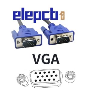

VGA
VGA and HDMI (High-Definition Interactive Media Interface) are two distinct video transmission protocols with notable advancements and features. VGA is a more well-known analog standard that transmits what are essentially video signals and is frequently seen in older computers and screens.
Because VGA uses an analog flag, it is more vulnerable to impedances and signal degradation over long distances.
Additionally, VGA supports lower resolutions than current benchmarks, typically reaching a maximum of 1920×1080, with less clarity because of signal change.
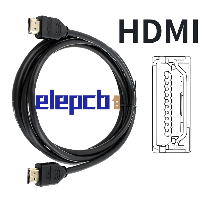
HDMI
However, as HDMI is a digital interface that carries both high-definition video and sound information, it is the recommended choice for contemporary TVs, game consoles, and PCs. HDMI offers very clean images without the limitations of analog transmission and supports higher resolutions, including 4K and 8K.
For improved interactive media interaction, it also activates cutting-edge capabilities like Bend (Sound Return Channel), HDCP encryption, and CEC (Consumer Electronic Control). HDMI connectors are perfect for skinny, high-tech devices because they are significantly smaller than VGA connectors.
DisplayPort
DisplayPort (DP), a high-performance computer interface for transferring audio and visual signals, is widely utilized in professional performances, gaming sets, and computer screens. DP offers higher refresh rates, multiple screen affiliations by daisy-chaining, and flexible matching enhancements like FreeSync and G-Sync for more fluid graphics, in contrast to conventional VGA and more consumer-focused HDMI.
It also supports incredibly high resolutions, like 8K at 60Hz, which makes it perfect for high-end gaming and professional illustration work. DP’s tiny, secure connector and data and control transfer capabilities continue to make it a popular choice for high-performance screens and workstations.
Applications of Pin VGA PCBs
Legacy Computer Systems
VGA interface is still essential for more established PCs and portable workstations, therefore Pin VGA PCBs are essential for maintaining screen compatibility.
Industrial and Embedded Systems
Because of its broad back and solidity, VGA is used to show yield in several mechanical gears and inserted frameworks.
Connectors and AV Converters
Signal change sheets that translate VGA signals into other groups, including HDMI or composite video, contain stick VGA PCBs.
DIY and Custom Display Projects
Pin VGA PCBs are used by do-it-yourselfers and hardware enthusiasts to create arcade machines, arcade gaming setups, and retro gaming consoles.
7 Verification Solutions for VGA Connector
| Category | Detail |
| PCB Simulation Tools | Keysight ADS: Eye Diagram Analysis of RGB Signals Altium Signal Integrity: Quick check of synchronized signal timing |
| Free 3D Model Library | TraceParts: STEP model of standard VGA connector GrabCAD: Detailed model download with pinout structure |
| Test Fixture | Homemade VGA Loop Test Board: Verify PCB Conductivity Hot air gun local heating method: 150 ℃ heating detection of solder joint cracking (rework analysis) |
| Extended Resource | Standards Document: IEC 807-2 (International Standard for D-Sub Interface) KiCad Scripting Tool: Interactive HTML BOM (assembly visual inspection) |
Method 1: Paper-based Verification
Step 1: KiCad Export Specification:
- Package export check “Exclude pads from outline” (to avoid pad interference with the outline line)
- Export format selection PDF (vector graphics) rather than SVG (some printers analyze SVG scaling errors)
Step 2: Mirroring and Scaling Calibration:
- FreeCAD accurate scaling:
					# Enter the scaling in the Python console (example: 1:1 conversion to actual size)
App.ActiveDocument.getObject("Connector").Scale = (25.4/72, 25.4/72, 25.4/72)  # DPI Conversion formula
Printer Calibration:
- Print a 10mm scale line, measure the actual length with a vernier caliper, and calculate the scaling factor (e.g., 9.8mm after printing, then scaling ratio = 10/9.8 ≈ 1.0204)
Step 3: Reinforcement of Hole Comparison:
- Hole Drill Locator: Use the center punch (Φ0.5mm) available at hardware stores to pre-drill the locating pits to reduce drilling offset.
- Error analysis tool:
- Open source software ImageJ: Measure the pixel-level deviation after scanning the paper mold (scale needs to be set).
- Qualification standard: pin spacing error <0.08mm, shell positioning hole error <0.15mm.
Method 2: 3D Printing Verification
- Insertion Force Test: Add spring scale hook slots on both sides of the connector (reserved for 3D printing) to quantify the insertion force (standard VGA insertion force should be ≤30N).
- Local Reinforcement Structure: Add honeycomb padding to the locating post and snap area (save material and increase strength at the same time).
| Material | Scenarios | Suggested Printing Parameters | Costs/hour |
| PLA | Rapid verification of form-fit | Layer height 0.1mm, 20% fill rate | 0.07 |
| PETG | Plug resistance test (100 times) | Nozzle temperature 235°C, hot bed 80°C | 0.11 |
| Nylon | High temperature environment simulation | Airtight chamber + desiccant, nozzle 260°C | 0.36 |
Method 3: Laser Cut FR4 Test Board
Step 1: Gerber Layer Configuration:
- Cuts, Drills and Pads only.
- Pads are designed as cross-hairs (1mm OD center holes) for easy microscope alignment measurements.
Step 2: Low-cost Prototyping Techniques:
- Low-cost prototyping tips: Specify “structural verification only, no electrical testing required” in the order memo line to the vendor to get a certain degree of price reduction.
- Jigsaw design: Arrange 5 VGA packages in a 10×10cm board to maximize the use of preferential size.
Step 3: Real Test Data Analysis Tools:
- Open source tool OpenCV: Automatic identification of pad and drill deviations with Python scripts.
					import cv2
img = cv2.imread("test_board.jpg")
gray = cv2.cvtColor(img, cv2.COLOR_BGR2GRAY)
circles = cv2.HoughCircles(gray, cv2.HOUGH_GRADIENT, 1, 20, param1=50, param2=30, minRadius=10, maxRadius=20)
# Comparison of output center coordinates with theoretical values
Method 4: Desktop-level CNC Engraving
| Machining Part | Tool Type | Feed Rate | Depth Strategy |
| Pad engraving | 0.2mm V-type cutter | 200mm/min | Layered cutting (0.1mm/layer) |
| Through-hole drilling | 0.6mm Carbide Drill | 300mm/min | Pecking drilling (0.5mm) |
FlatCAM advanced configuration:
- Chamfering of pads: add Chamfer Toolpath after Gerber import (45° chamfering to minimize burrs)
- Tool life monitoring: set up Z-axis compensation formula to automatically adjust the depth of cut according to the machining time (compensates for wear).
| Issues | Reason | Solution |
| Pin cannot be inserted | Pad XY offset | Paper – based + diagonal measurement with vernier calipers. |
| Insufficient solder creep | Wrong aperture/pad ratio | Observe after CNC engraving with flux coating. |
| Shaking of the Case | Positioning post diameter deviation | 3D printing + plug gauge test. |
Method 5: Silicone Molding
- Liquid silicone is used to duplicate the connector pins and then cured as a “flexible gauge” to check the pad position.
- Cost: $7.14 (can be reused more than 10 times)
Method 6: Projector Comparison
- Project the KiCad designed package onto the actual PCB and compare with a laser calibrated projector (e.g. UNIC UC-40).
- Accuracy: ±0.05mm (require darkroom environment)
Method 7: 3D Model Integration and Mechanical Verification
Model Format Conversion Process
					# VRML convert to STL(Compatible with KiCad 3D Viewer)
brew install openscad  # macOS
openscad -o connector.stl -D 'import("connector.wrl");' dummy.scad
Reorienting the Model: Correcting the Coordinate System in FreeCAD to Match KiCad Requirements
Interference check points
- Housing to peripheral component spacing (recommended ≥ 1.5mm)
- Distance between screw posts and PCB board edge (to prevent assembly stress)
Troubleshooting with VGA Pinout
Case 1: Color Shift of Image
Phenomenon: Purple is visible on the blue channel and the red is not strong.
Underlying Reasons:
- The BLUE signal line (Pin 3) is merely 0.2 mm away from the adjacent ground wire. Signal weakening is due to capacitive coupling.
- The impedance calculation tool was not employed, and the measured impedance was 58Ω, not the required 75Ω.
Solutions:
- Re-wire and make the line spacing 0.5 mm.
Case 2: Hot-Plugging Damage
Phenomenon: After multiple VGA cable pluggings and unplugging, the interface does not work.
Underlying Reasons:
- The hot plugging protection circuit is not built. The maximum inrush current is 2A, which is more than the 1A-rated pin.
- Bond between pad and PCB substrate is weak (bonding must be modified to immersion gold ENIG surface treatment).
Solutions:
- Put a PTC self-recovering fuse like RUEF300.
- Add 0.5 mm non-metallized anchor holes into the pad.
Case 3: Mechanical Breakage
Phenomenon: The VGA interface detaches from the PCB.
Underlying Reasons:
- It only uses solder joints for mounting, without the use of screw holes or reinforcement ribs.
- The pad is small (0.6 mm hole diameter and 1.0 mm pad).
Solutions:
- Insert M3 screw fixing holes and pre-embed copper pillars on both sides of the connector.
| Issues | Reason | Solution |
| Unable to insert pins | Wrong package mirroring | Check top/bottom layer properties |
| Bad tinning of pads | Pad size too small | Increase pad extents ≥ 0.3mm |
| Too much gap between case and PCB | 3D model Z-axis offset | Adjust STEP model origin |
| Misaligned screw holes | Imperial/Metric unit confusion | Harmonize design with millimeter units |
Conclusion
Pin VGA PCBs continue to be useful in a variety of applications despite the growing popularity of sophisticated interfaces. Their reliable design maintains interoperability with legacy regimes while ensuring consistent video signal delivery. Whether you are working on mechanical equipment, transformation sheets, or specialized projects, knowing VGA PCB layout guidelines can help you get the best performance out of your video applications.
Need more guidance? Contact ELEPCB for more information or just get a quote!
FAQs
A1: There is no specification of power output given in the standard specification of the VGA interface, and its basic responsibility is limited to carrying control synchronization signals and analog video signals.
In the first place, the power-supplying stable VGA standard interface and signal lines of the existing carrying capability have only just enough capacity for supplying the requirement for video transmission.
Also, according to the IEEE 1284-1994 VGA interface standard, no power output pin exists in the electrical specification of the 15-pin interface, as can be seen in the table below:
| Pin num | Voltage Range | Current-carrying |
| 1(RED) | 0-0.7Vp-p | ≤10mA |
| 2(GREEN) | 0-0.7Vp-p | ≤10mA |
| 14(VSYNC) | 0-5V(TTL) | ≤20mA |
| DDC | 3.3V/5V(I²C) | ≤50mA |
However, there are examples of non-compliance with the specifications, and some of the devices are not fully power-efficient in transmitting their power via pin-multiplexing techniques:
- Power supply of the DDC channel
Technical concept: using the DDC (Display Data Channel) I²C bus voltage (commonly 5V ± 5%) to supply power to the low-power chip.
Typical application: In the VGA adapter to HDMI, the power supply for the CH7101B chip is taken from Pin9 (+5V) of the VGA interface, and its supply current is approximately 45mA (close to the I²C bus limit). Limitations: When the cables are attached to it, the supply power will not be able to supply the I²C bus.
Limitations: If the cable length of the connected cable exceeds 5 meters, the voltage drop will cause the converter to operate abnormally, e.g., screen flicker, audio distortion and so on.
- USB composite interface power supply
There are certain industrial devices (e.g., Advantech industrial controllers) that utilize VGA + USB composite port:
- Structural design: USB power contacts integrated into the metal housing of the VGA interface, with support for 5V/2A output.
- Applications: Used to power the touch screen control module for simplifying the quantity of cables by supplying power and video signal supply.
After load testing of Pin9 (DDC 5V) of three normal VGA interfaces, we also found that even though with non-standard power supply, the actual power supply capacity of the VGA interface will never go beyond 100mA, it is therefore only for micro-power devices.
| Equipment | No-load Voltage | 100mA Load Voltage | Maximum Continuous Current |
| Dell OptiPlex 7050 | 5.02V | 4.15V | 82mA |
| Lenovo ThinkCentre M720q | 4.98V | 3.89V | 68mA |
| Huawei US228 Server | 5.11V | 4.32V | 95mA |
And if there is a critical need for stable power supply through the VGA interface, the following technical measures can be adopted:
- Active signal converter
Use an external power adapter (e.g., Sabrent USB-C to VGA adapter) to provide 5V/1A independent power via the USB interface to avoid utilizing the VGA interface power.
- PoVGA Technology Extension
Industrial equipment (such as Extron POVG 100) through signal line coupling power supply, in the RGB channel superimposed 48V DC, supports 20W power transmission, but needs to match with special receiver end equipment.


CONTACT US




 English
  Italian
  Hungarian