

Table of Contents
What is BGA in PCB?
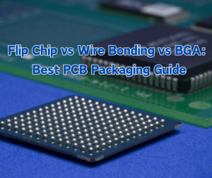
Ball Grid Array is an innovative surface mount packaging technology that has revolutionized the way electronic components are mounted onto printed circuit boards.
Unlike traditional through-hole components, BGAs use an array of solder balls placed beneath the component, forming a grid-like pattern.

Each solder ball serves as a connection point between the integrated circuit and the PCB. This arrangement not only offers a more compact design but also improves the electrical connection between the chip and the board. The solder balls are typically made of lead-based or lead-free solder, depending on environmental regulations and specific application requirements.
Types of BGA Package

BGA Package Comparison: Critical Specifications
| Parameter | PBGA | CBGA | TBGA | FCBGA | µBGA |
| Pitch Range | 0.8-1.0mm | 1.0-1.27mm | 0.5-0.8mm | 0.4-1.0mm | 0.3-0.4mm |
| Substrate | Plastic | Ceramic | Polyimide | Organic/Laminate | Flex Tape |
| Thermal Perf. | 15-20°C/W | 8-12°C/W | 18-25°C/W | 5-10°C/W | 22-30°C/W |
| Moisture Sens. | High (L3) | None (L0) | Medium (L2) | Low (L1) | High (L3) |
| I/O Density | Medium | Medium | High | Very High | Extreme |
Step-by-Step BGA Assembly Process

1. Die Process
2. Wire Bonding
3. Overmold / Encapsulation
4. Ball Attach Process
5. Singulation and Testing

Common BGA Assembly Defects and Their Prevention
- Solder Joint Voids
- Cause: Excess flux, improper reflow profile, or gas trapped during soldering.
- Solution: Enhance temperature ramp rate and use vacuum reflow or nitrogen environment to prevent voids.
- Head-in-Pillow (HiP) Defect
- Cause: Oxidized solder balls or uneven temperature, leading to incomplete wetting.
- Solution: Maintain component storage environment, inspect for reflow uniformity, and use fresh solder paste.
- Bridging and Short Circuits
- Cause: Improper solder or misplaced placement.
- Solution: Adjust stencil thickness, optimize volume solder paste, and ensure proper alignment during placement.
- Cold or Non-wet Joints
- Cause: Insufficient reflow temperature or unclean pads.
- Solution: Clean surfaces of PCB, verify flux activity, and have correct reflow profiles.
- Cracked or Broken Solder Balls
- Cause: Thermal cycling stress or warpage of the PCB.
- Solution: Use materials with matched CTE (Coefficient of Thermal Expansion) and control cooling rate to restrict stress.
Case Study: BGA Hot Tear
The solder balls are located above the chip end. The cracks represent delamination between the solder ball and internal substrate layers (between substrate or die attach). This represents internal thermal tearing (internal interface failure caused by thermal stress), distinct from typical PCB pad detachment or solder joint cold soldering.
Cracks appearing at the upper interface of the chip side suggest this phenomenon resulted from stresses generated within the BGA package structure itself during thermal shock. This can be identified as a classic case of “chip-side thermal tearing,” particularly prone to occur in large chips, large packages, and BGAs with thick substrates.
- Verify the BGA’s internal structure with suppliers—specifically regarding the presence of cavities or stress relief designs.
- Optimize reflow soldering parameters by reducing peak temperatures and extending dwell times to prevent thermal stress accumulation within the package.
Solving BGA Assembly Challenges: ELEPCB's Proven Approach
As electronic devices become more complex and miniaturized, the intricacies of BGA assembly become increasingly critical to address.
Incorporating advanced technology, skilled engineering, and stringent quality control, ELEPCB’s BGA assembly process is a testament to our commitment to excellence.

Thermal Considerations
Efficient heat dissipation is a hallmark of BGA technology. However, managing heat distribution during the assembly process is crucial to prevent solder joint failures and ensure the long-term reliability of the device. Uneven heating during reflow soldering can lead to thermal stresses that compromise solder connections, resulting in electrical failures.
It’s imperative to carefully control the reflow soldering process to achieve uniform heat distribution and proper solder wetting, ensuring strong and durable connections.
Inspection and Rework Challenges
The concealed nature of BGA solder joints poses challenges when it comes to inspection and rework. Unlike traditional packages with visible leads, BGA solder joints are hidden beneath the package, making visual inspection difficult. X-ray inspection becomes crucial to assess the quality of solder connections and identify potential defects such as voids, insufficient solder, or misalignment.
Additionally, in cases of faulty connections, reworking BGA packages demands specialized equipment and expertise to avoid damaging neighboring components.

Integrity of Solder Balls
BGA assembly involves intricate soldering of numerous small solder balls. Ensuring the integrity of each solder ball and achieving consistent soldering across the entire package can be a challenge. Factors such as solder paste quality, accurate placement, and controlled reflow profiles play a vital role in achieving reliable solder connections.
Alignment and Placement Precision
The precise placement of BGA packages onto the PCB is critical for achieving optimal electrical connections. Misalignment, even by a fraction of a millimeter, can result in poor connections or shorts. Advanced automated assembly equipment and accurate placement algorithms are essential to achieve the necessary alignment precision.

Conclusion
BGA PCB assembly has revolutionized electronic manufacturing, enabling compact, high-performance devices across various industries. ELEPCB’s expertise in BGA assembly, backed by advanced technology and a skilled team, ensures the delivery of reliable, high-quality BGA PCBs that drive innovation forward. Contact us today to discuss your BGA PCB assembly needs and witness the future of electronics manufacturing with ELEPCB.
FAQ
Learn More about BGA:
What is BGA Electronics in PCB?


CONTACT US





 English
  Italian
  Hungarian